

Phantom Powered Microphone Preamplifier – Low Noise – Professional Quality
- Rajkumar Sharma
- 542 Views
- moderate
- Tested
- SKU: EL129554
- Quote Now
- 0 Likes

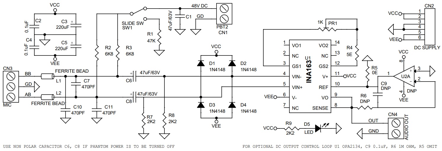
The project presented here is a professional quality Phantom powered Microphone pre-amplifier. The project is built using the INA163 chip from TI. The Chip is a very low-noise, low-distortion, monolithic instrumentation amplifier. R2 and R3 provide a current path for a conventional 48V phantom power source for a remotely located microphone. A slide switch SW1 allows phantom power to be disabled. C6 and C8 block the phantom power voltage from the INA163 input circuitry. Additional input protection against ESD and hot-plugging, four 1N4148 diodes D1, D2, D3, D4 connected from the input to supply lines. R7 and R8 provide a path for the input bias current of the INA163. Gain is set with a variable resistor, PR1, in series with R4. R4 determines the maximum gain. The total resistance, R4 + PR1, determines the lowest gain. A special reverse-log taper potentiometer for PR1 can be used to create a linear change (in dB) with rotation. LED D5 is used as a power indicator. L1, L2, C7, C10, and C11 components protect the inputs from EMI and RFI noise.
Optional DC Output Control Loop
Input offset current (typically 100nA) creates a DC differential input voltage that will produce an output offset voltage. This is generally the dominant source of the output offset voltage. With a maximum gain of 1000 (60dB), the output offset voltage can be several volts. This may be entirely acceptable if the output is AC-coupled into the subsequent stage. An optional circuit is provided to tackle this problem. An inexpensive FET-input op-amp U2A in a feedback loop drives the DC output voltage to 0V. Op-Amp is not in the audio signal path and does not affect signal quality.
Install the Following Components for DC Output Control Loop
- U2A = OPA2134 SOIC8
- C9 = Ceramic Capacitor 0.1uf/50V SMD Size 0805
- R6 1Mega Ohm 5% SMD Resistor Size 0805
- Omit Resistor R5
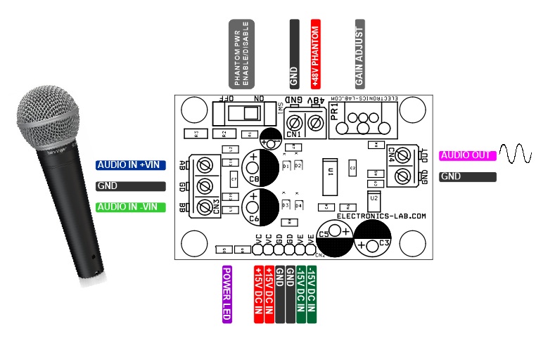
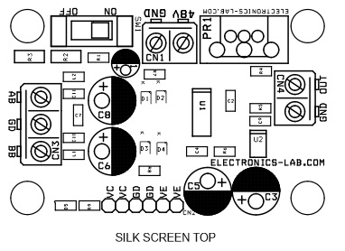
Connections and Other Details
- CN1: Pin 1 = +48V DC Phantom Power Input, Pin 2= GND
- CN2: Pin 1-2 = VCC +15V DC, Pin 2-3 = GND, Pin 4-5 VEE -15V DC
- CN3: Pin 1 = BB Microphone – VIN, Pin 2 = GND, Pin 3 = AB Microphone + VIN
- CN4: Pin 1 = Audio Output, Pin 2 = GND
- D5: Power LED
- SW1: Phantom Power Enable/Disable Switch
Note: Non-polarized capacitors should be used for C1 and C2 if phantom power is to be disabled.
Features
- Power Supply Dual 15V DC (+/-15V DC)
- On Board Power LED
- Slide switch for Phantom Power Enable/Disable
- 3 Pin Screw Terminal for Microphone Connections
- 2 Pin Screw Terminal for Audio Output
- 2 Pin Screw Terminal for Phantom Power Input 48V DC
- 6 Pin Male Header for Power Input
- Gain Up to 1000/V (60dB)
- Potentiometer PR1 Gain Adjust
- PCB Dimensions 60.17 x 39.85mm
- 4 x 3mm Mounting Holes
Schematic
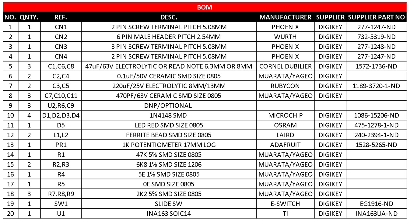
Parts List
| NO. | QNTY. | REF. | DESC. | MANUFACTURER | SUPPLIER | PART NO |
|---|---|---|---|---|---|---|
| 1 | 1 | CN1 | 2 PIN SCREW TERMINAL PITCH 5.08MM | PHOENIX | DIGIKEY | 277-1247-ND |
| 2 | 1 | CN2 | 6 PIN MALE HEADER PITCH 2.54MM | WURTH | DIGIKEY | 732-5319-ND |
| 3 | 1 | CN3 | 3 PIN SCREW TERMINAL PITCH 5.08MM | PHOENIX | DIGIKEY | 277-1248-ND |
| 4 | 1 | CN4 | 2 PIN SCREW TERMINAL PITCH 5.08MM | PHOENIX | DIGIKEY | 277-1247-ND |
| 5 | 3 | C1,C6,C8 | 47uF/63V ELECTROLYTIC OR READ NOTE 6.3MM OR 8MM | CORNEL DUBILIER | DIGIKEY | 1572-1736-ND |
| 6 | 2 | C2,C4 | 0.1uF/50V CERAMIC SMD SIZE 0805 | MUARATA/YAGEO | DIGIKEY | |
| 7 | 2 | C3,C5 | 220uF/25V ELECTROLYTIC 8MM/13MM | RUBYCON | DIGIKEY | 1189-3720-1-ND |
| 8 | 3 | C7,C10,C11 | 470PF/63V CERAMIC SMD SIZE 0805 | MUARATA/YAGEO | DIGIKEY | |
| 9 | 3 | U2,R6,C9 | DNP/OPTIONAL | |||
| 10 | 4 | D1,D2,D3,D4 | 1N4148 SMD | MICROCHIP | DIGIKEY | 1086-15206-ND |
| 11 | 1 | D5 | LED RED SMD SIZE 0805 | OSRAM | DIGIKEY | 475-1278-1-ND |
| 12 | 2 | L1,L2 | FERRITE BEAD SMD SIZE 0805 | LAIRD | DIGIKEY | 240-2394-1-ND |
| 13 | 1 | PR1 | 1K POTENTIOMETER 17MM LOG | ADAFRUIT | DIGIKEY | 1528-5265-ND |
| 14 | 1 | R1 | 47K 5% SMD SIZE 0805 | MUARATA/YAGEO | DIGIKEY | |
| 15 | 2 | R2,R3 | 6K8 1% SMD SIZE 1206 | MUARATA/YAGEO | DIGIKEY | |
| 16 | 1 | R4 | 5E 1% SMD SIZE 0805 | MUARATA/YAGEO | DIGIKEY | |
| 17 | 1 | R5 | 0E SMD SIZE 0805 | MUARATA/YAGEO | DIGIKEY | |
| 18 | 3 | R7,R8,R9 | 2K2 5% SMD SIZE 0805 | MUARATA/YAGEO | DIGIKEY | |
| 19 | 1 | SW1 | SLIDE SW | E-SWITCH | DIGIKEY | EG1916-ND |
| 20 | 1 | U1 | INA163 SOIC14 | TI | DIGIKEY | INA163UA-ND |
Connections
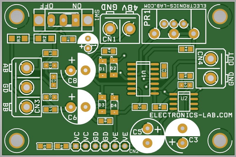
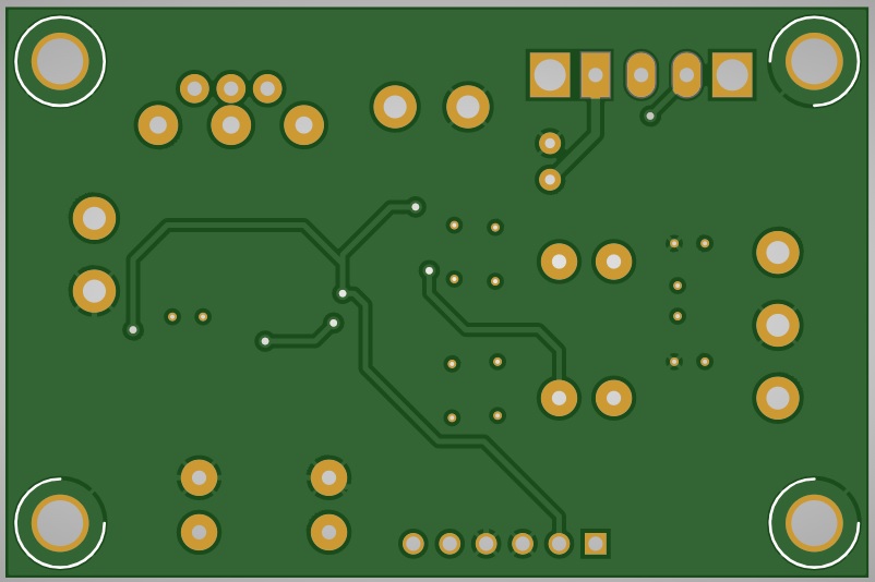
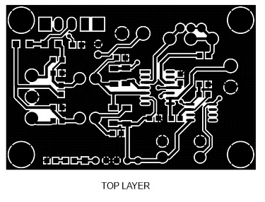
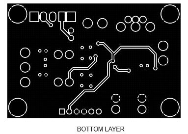
Gerber View
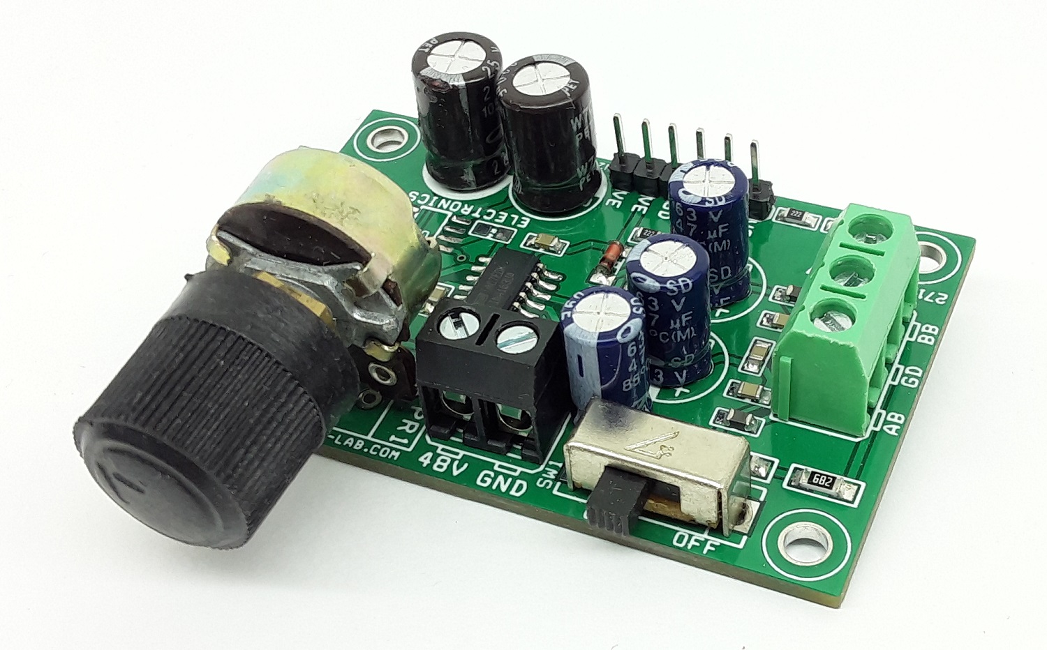
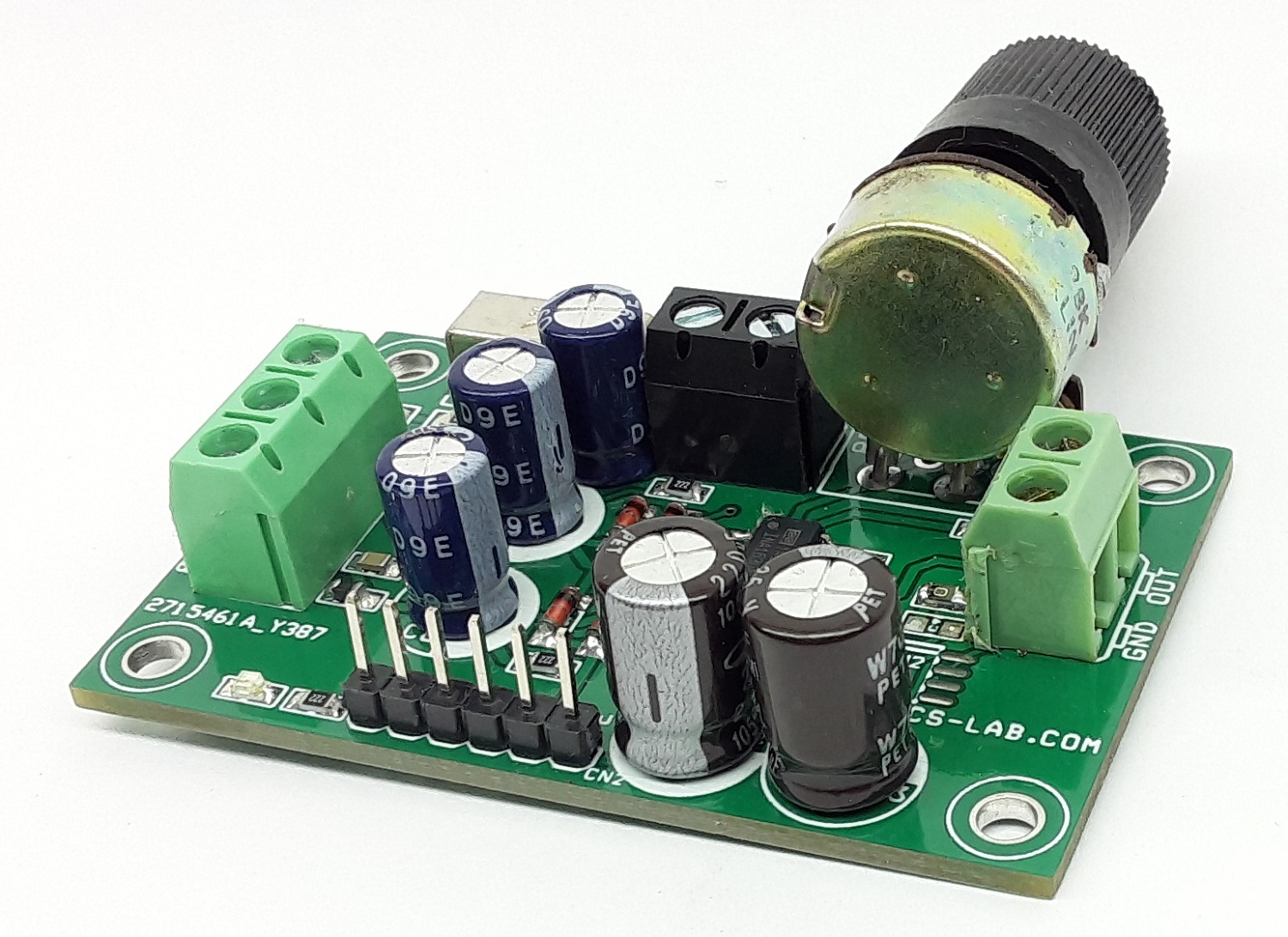
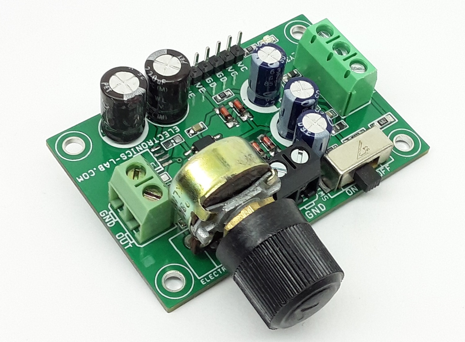
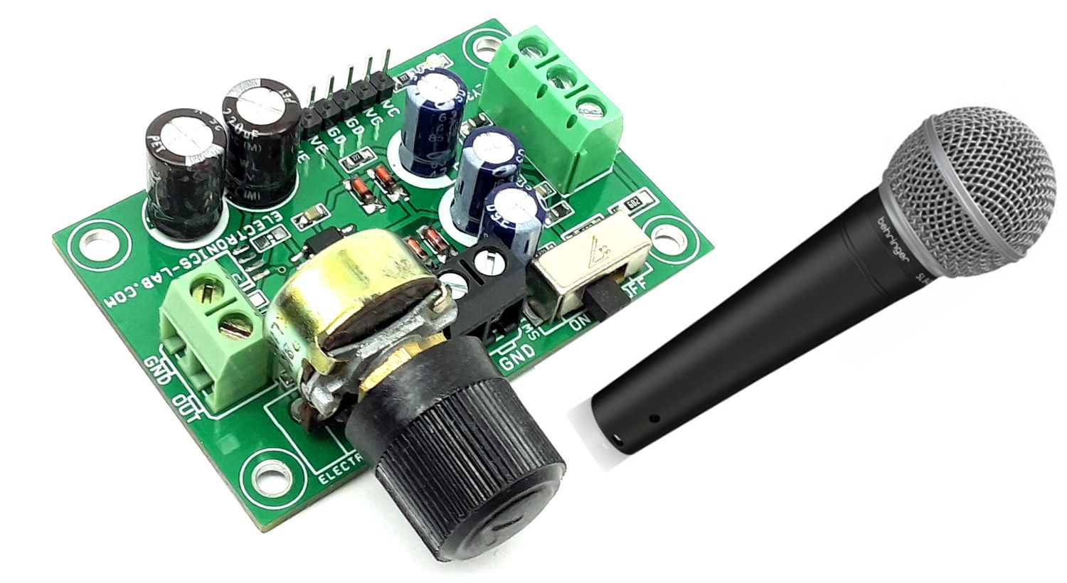
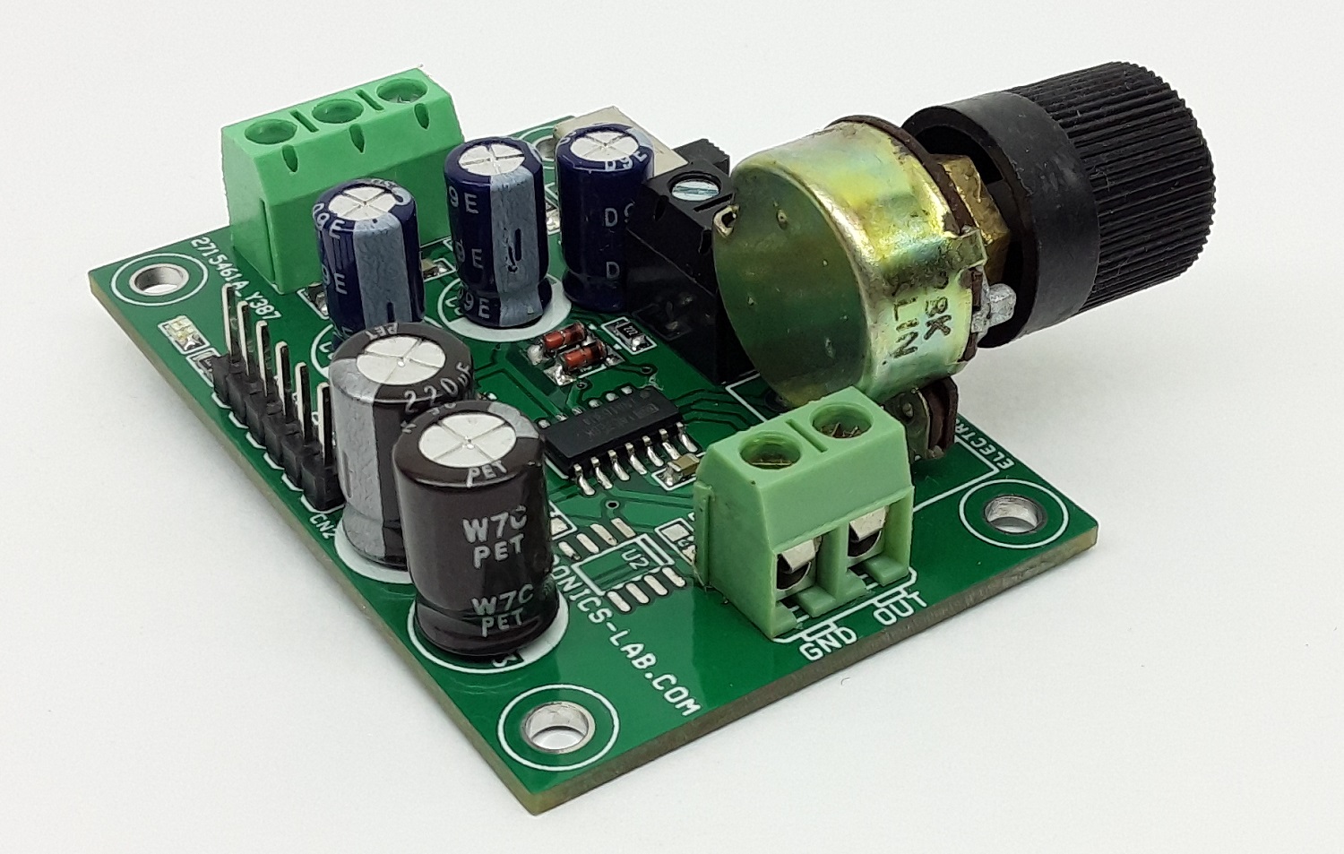
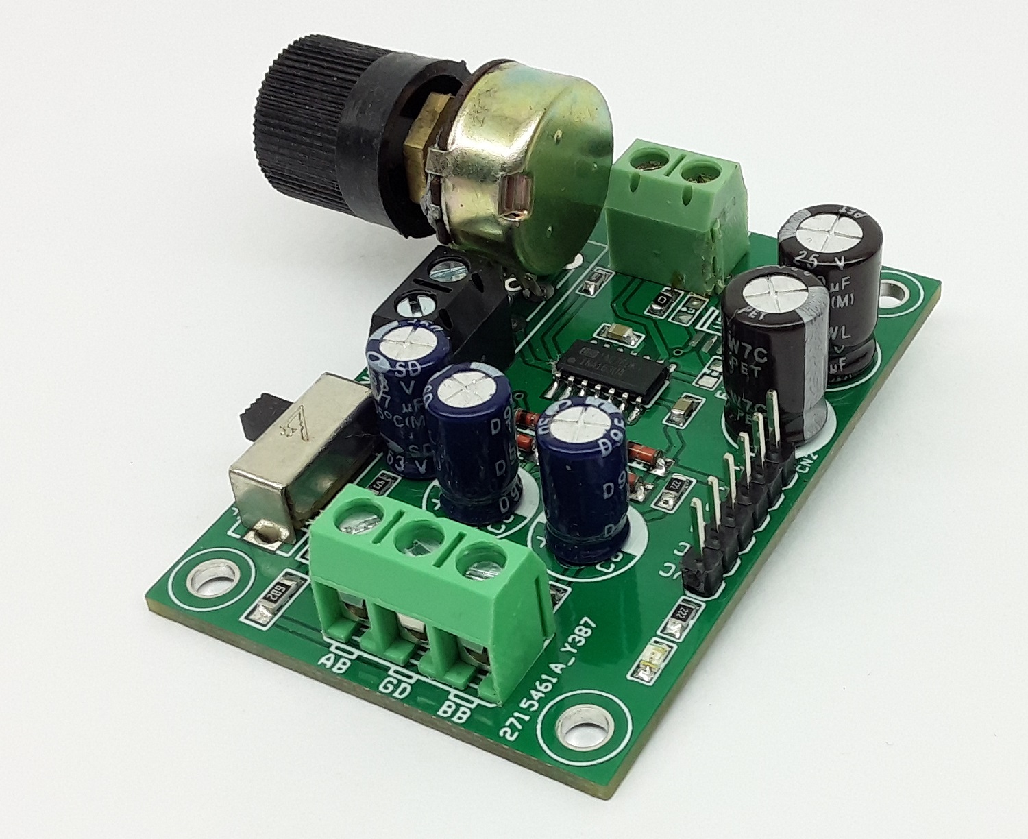
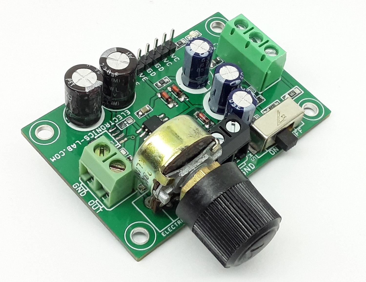
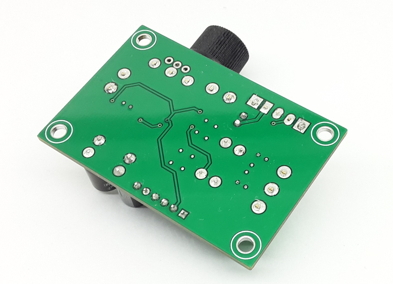
Photos
Video
Datasheet
Please follow and like us:


PCB


Subscribe
Login
0 Comments