

High Current Half-Bridge with Over Current & Voltage Feedback for Step Down DC-DC Converter
- Rajkumar Sharma
- 398 Views
- medium
- Tested
- SKU: EL121012
- Quote Now
- 0 Likes

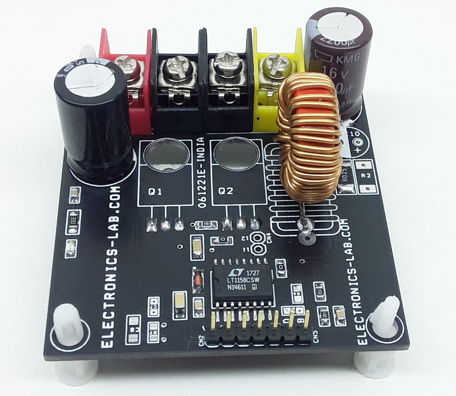
This project enables the user to create a high current DC-DC converter. The project consists of a high current inductor, high current low voltage 2 x MOSFETs, half-bridge driver LT1158 chip, voltage feedback using onboard R9 and R10 resistor dividers, shunt resistor for overcurrent shut-down. The project has all the required components to create a high current step-down DC-DC converter, refer to the datasheet of LT1158 chip for components selection. The Half-bridge requires a PWM input signal, Arduino or another microcontroller/DSP can be used as a host to generate PWM signal and control enable and fault conditions.
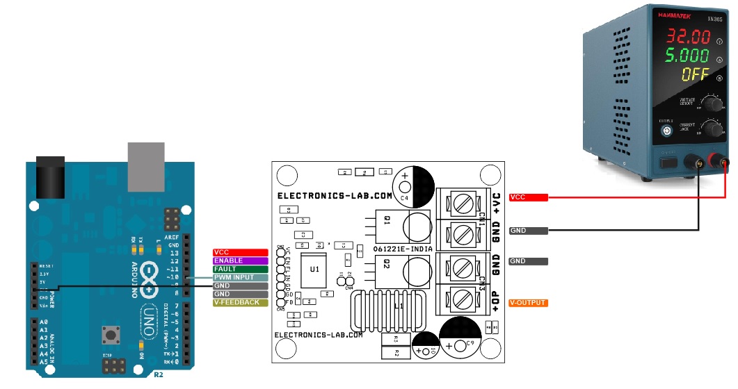
Arduino Example Code helps users to test the board, the project provides output approx. 5V/4Amps from input Supply 22-24V DC.
Applications
- DC-DC Converter
- High Current Solar Charger
- SLA Battery Charger
Key Features
- High Current Low Voltage 2 x MOSFET IRF540 (the user may Use Other Low Ohm MOSFET)
- Half-Bridge Driver LT1158 Chip
- L1 High Current Inductor Default 100uH/7.8Amp
- R2 and R3 Resistor for Current Sense, For Over Current Limit/Short Circuit – Refer to Datasheet for R2, R3 Values.
- Fault: Open collector NPN output which turns on when V12 – V11 (Current Sense Pins) exceeds the fault conduction threshold.
- D3 LED for Output, D2 LED for Input Supply
- Voltage Feedback Output CN5, Resistor Divider R9, R10, C11
- Inputs and Fault Output CN2
- Operating Supply 12V to 30V DC (Input Supply Should Not Exceed 30V)
- PCB Dimensions 69.22 x 55.88 mm
Over Current Shutdown – Open collector, NPN output turns on when V12 – V11 (Current Sense Pins) exceeds the fault conduction threshold.
- For Internal Over Current Shutdown Use R7 and C8, Refer to Datasheet for Values
- For Host Controlled Shutdown Use Fault and Enable Pins
Voltage Feedback
- CN5, Feedback from Output using Resistor Divider R9 and R10, Use C11 for stability.
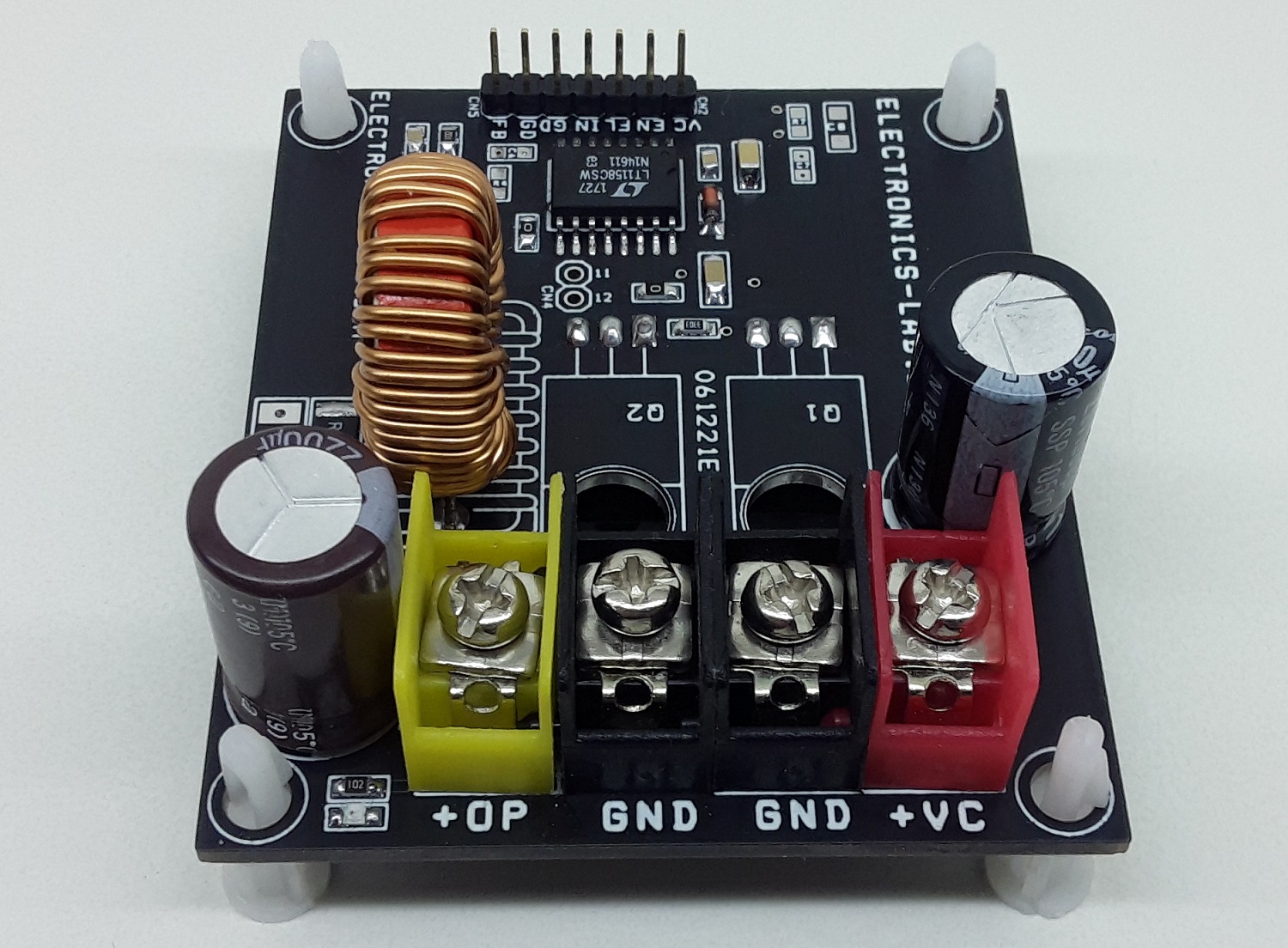
Connections: CN2
- Pin1 = VCC
- Pin2 = Enable – Pull Low to disable the Output
- Pin3= Fault Output – Goes Low when Over Current Condition Occurs
- Pin4= PWM Input 0 to 100Khz
- Pin5=GND
- Use R7 and C8 for Internal Over Current Shutdown, Refer to Datasheet of LT1158
Connections CN1
- Pin1 = VCC 12V to 30V Input
- Pin2 + GND
Connections CN3
- Pin1 = + Output
- Pin2= GND
CN4: Not Installed
Connections CN5
- Pin 1 = +Voltage Feedback Output
- Pin 2 = GND
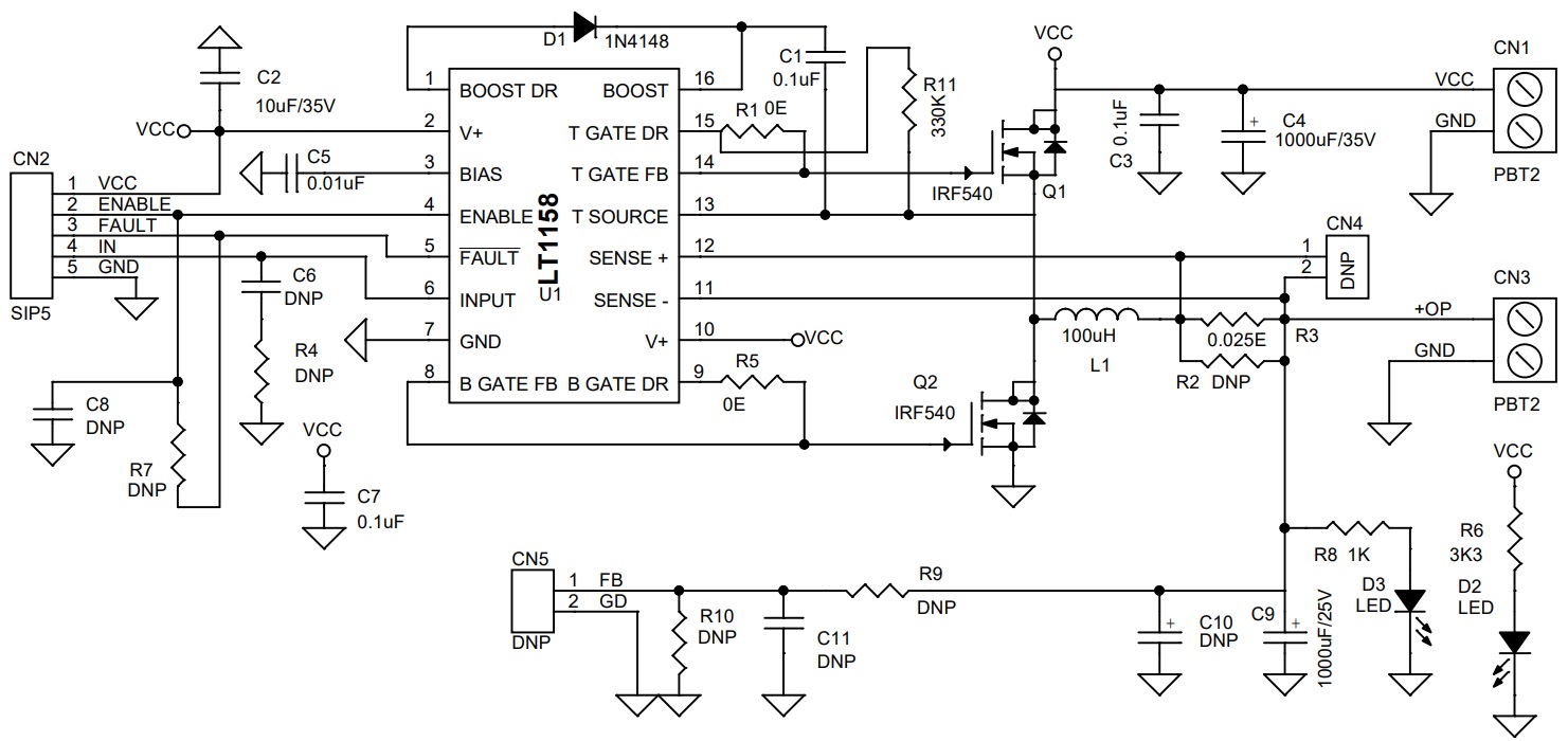
Schematic
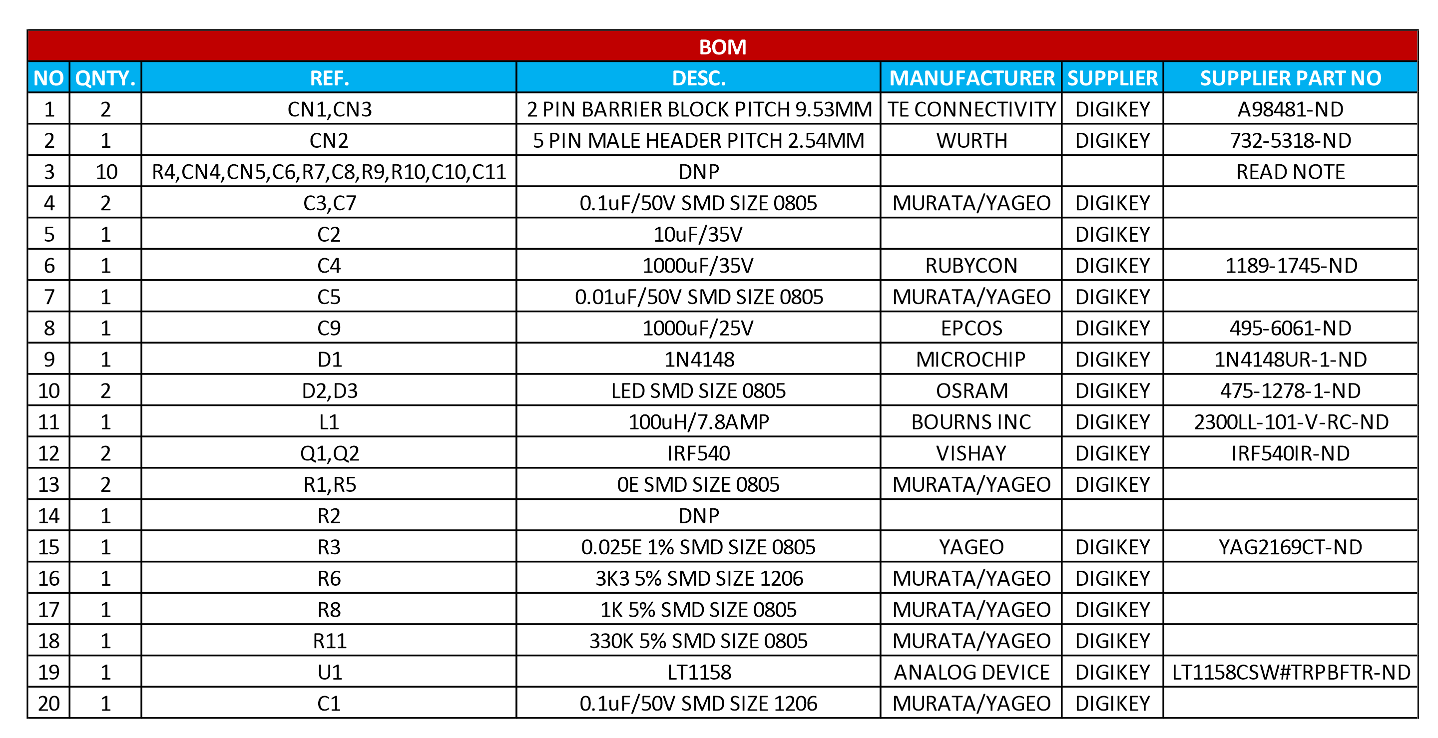
Parts List
| NO | QNTY. | REF. | DESC. | MANUFACTURER | SUPPLIER | PART NO |
|---|---|---|---|---|---|---|
| 1 | 2 | CN1,CN3 | 2 PIN BARRIER BLOCK PITCH 9.53MM | TE CONNECTIVITY | DIGIKEY | A98481-ND |
| 2 | 1 | CN2 | 5 PIN MALE HEADER PITCH 2.54MM | WURTH | DIGIKEY | 732-5318-ND |
| 3 | 10 | R4,CN4,CN5,C6,R7 | DNP | READ NOTE | ||
| C8,R9,R10,C10,C11 | DNP | READ NOTE | ||||
| 4 | 2 | C3,C7 | 0.1uF/50V SMD SIZE 0805 | MURATA/YAGEO | DIGIKEY | |
| 5 | 1 | C2 | 10uF/35V | DIGIKEY | ||
| 6 | 1 | C4 | 1000uF/35V | RUBYCON | DIGIKEY | 1189-1745-ND |
| 7 | 1 | C5 | 0.01uF/50V SMD SIZE 0805 | MURATA/YAGEO | DIGIKEY | |
| 8 | 1 | C9 | 1000uF/25V | EPCOS | DIGIKEY | 495-6061-ND |
| 9 | 1 | D1 | 1N4148 | MICROCHIP | DIGIKEY | 1N4148UR-1-ND |
| 10 | 2 | D2,D3 | LED SMD SIZE 0805 | OSRAM | DIGIKEY | 475-1278-1-ND |
| 11 | 1 | L1 | 100uH/7.8AMP | BOURNS INC | DIGIKEY | 2300LL-101-V-RC-ND |
| 12 | 2 | Q1,Q2 | IRF540 | VISHAY | DIGIKEY | IRF540IR-ND |
| 13 | 2 | R1,R5 | 0E SMD SIZE 0805 | MURATA/YAGEO | DIGIKEY | |
| 14 | 1 | R2 | DNP | |||
| 15 | 1 | R3 | 0.025E 1% SMD SIZE 0805 | YAGEO | DIGIKEY | YAG2169CT-ND |
| 16 | 1 | R6 | 3K3 5% SMD SIZE 1206 | MURATA/YAGEO | DIGIKEY | |
| 17 | 1 | R8 | 1K 5% SMD SIZE 0805 | MURATA/YAGEO | DIGIKEY | |
| 18 | 1 | R11 | 330K 5% SMD SIZE 0805 | MURATA/YAGEO | DIGIKEY | |
| 19 | 1 | U1 | LT1158 | ANALOG DEVICE | DIGIKEY | LT1158CSW#TRPBFTR-ND |
| 20 | 1 | C1 | 0.1uF/50V SMD SIZE 1206 | MURATA/YAGEO | DIGIKEY |
Connections
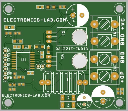
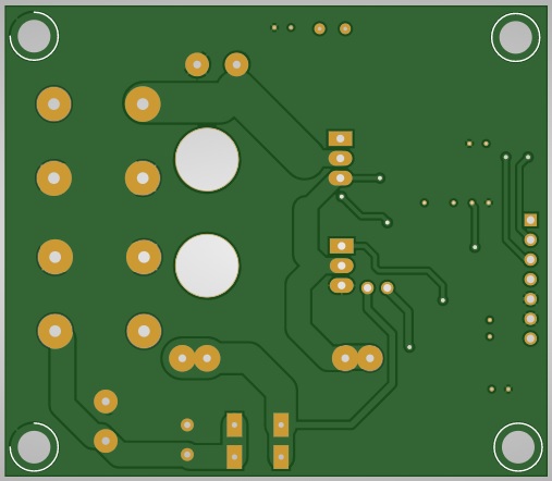
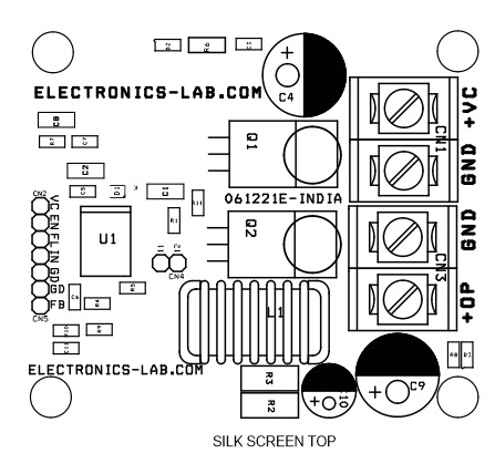
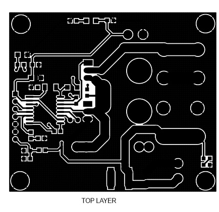
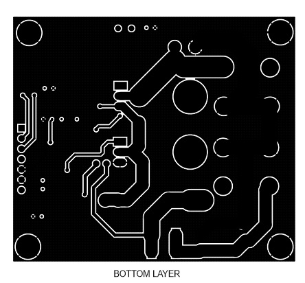
Gerber View
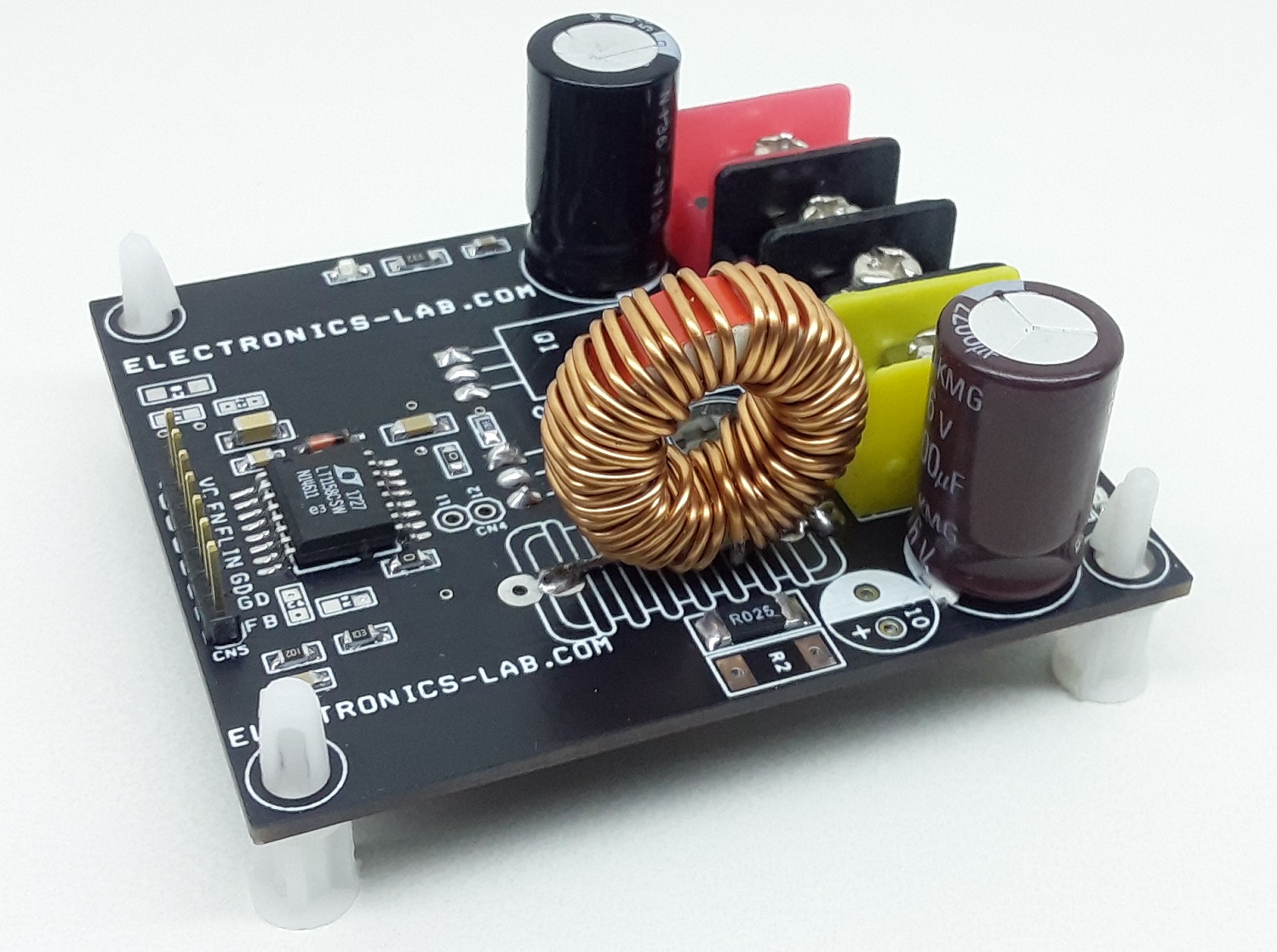
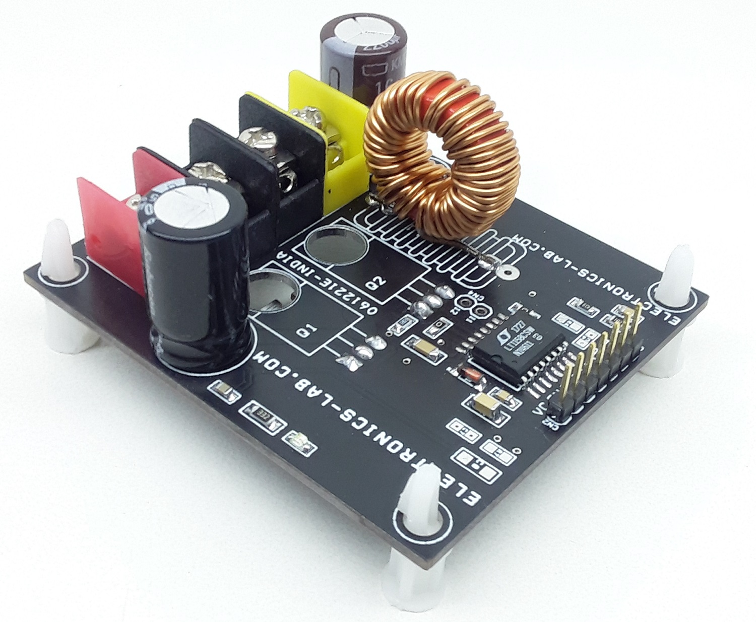
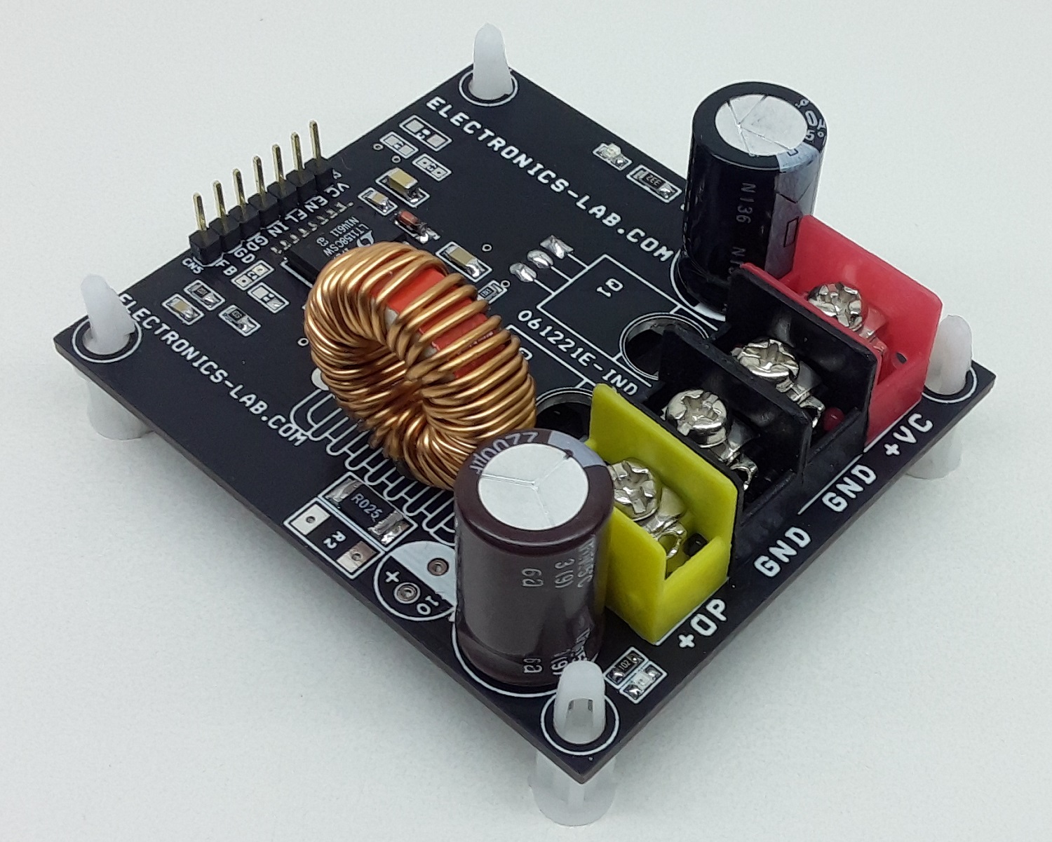
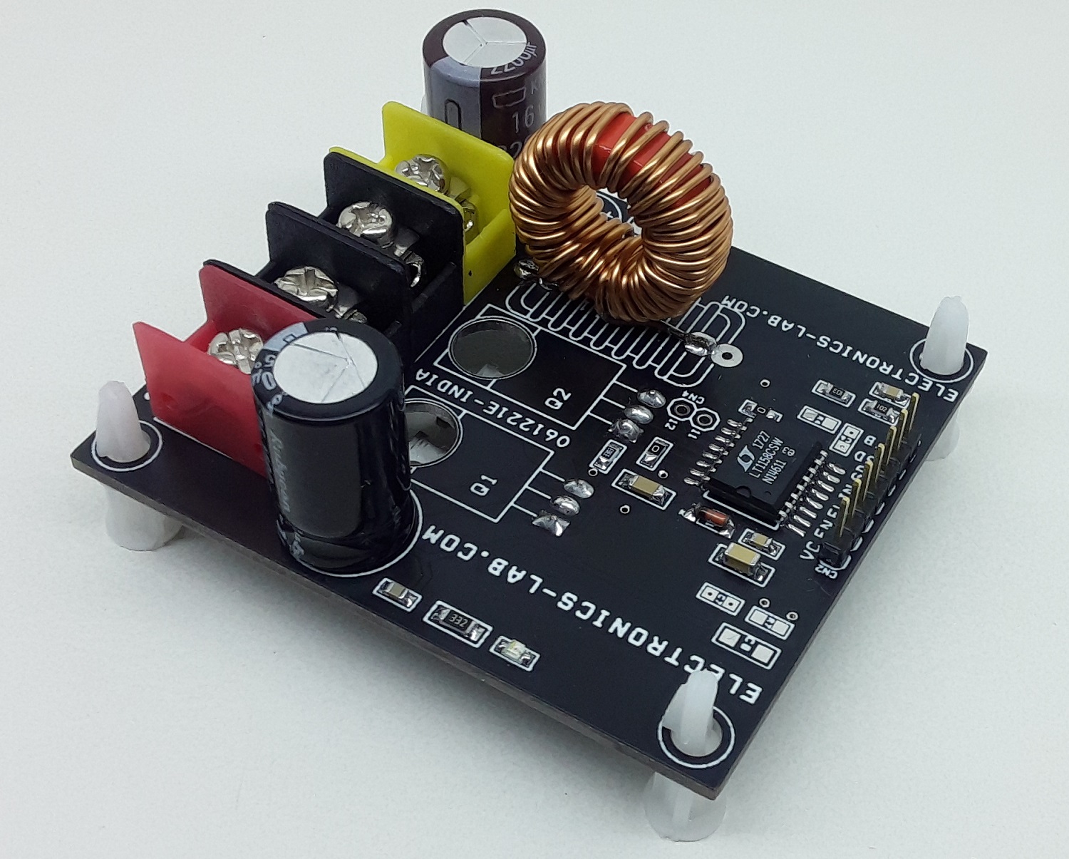
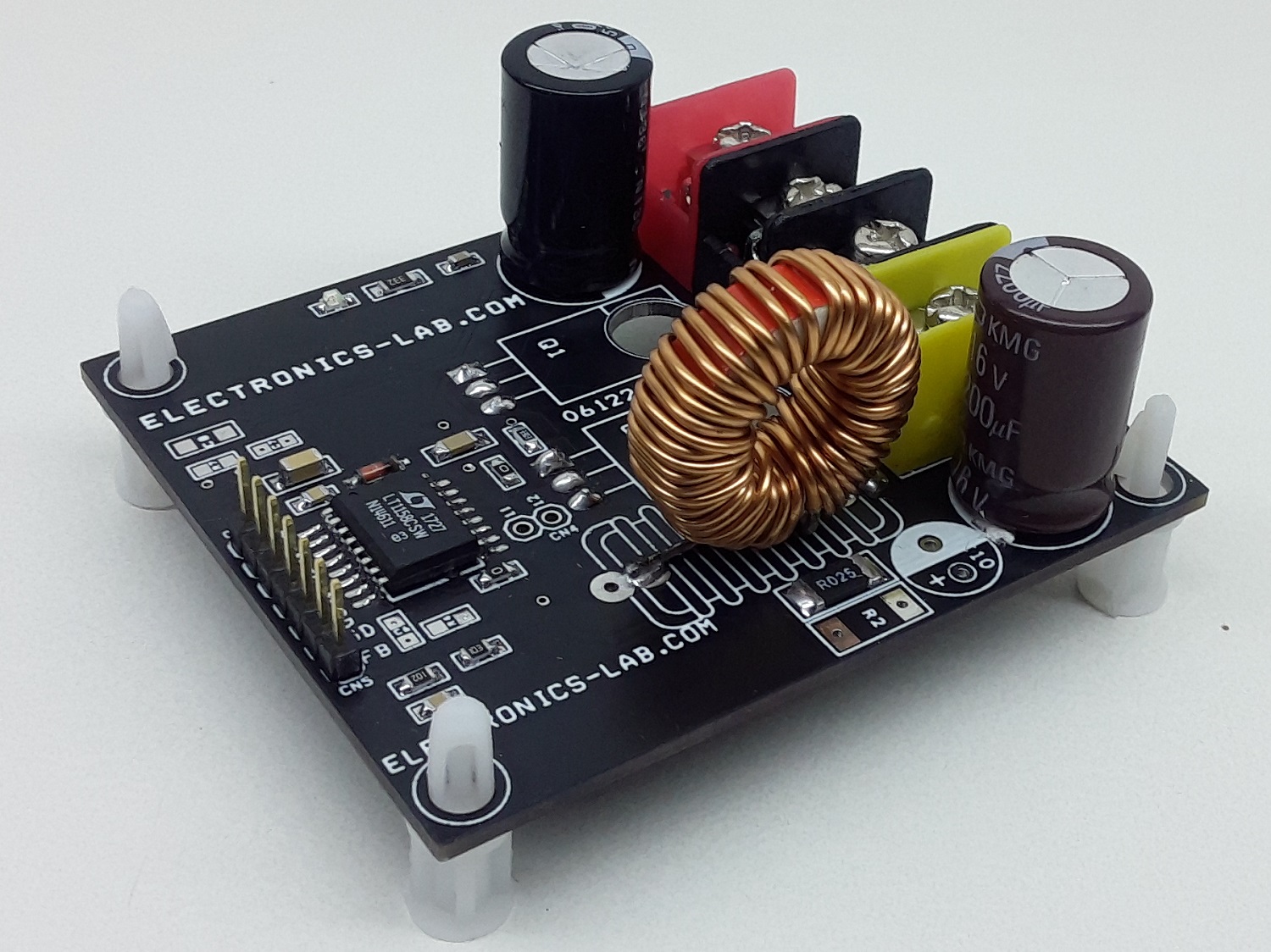
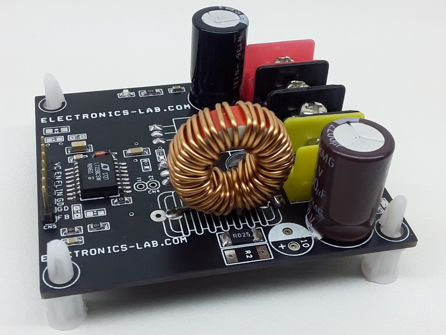
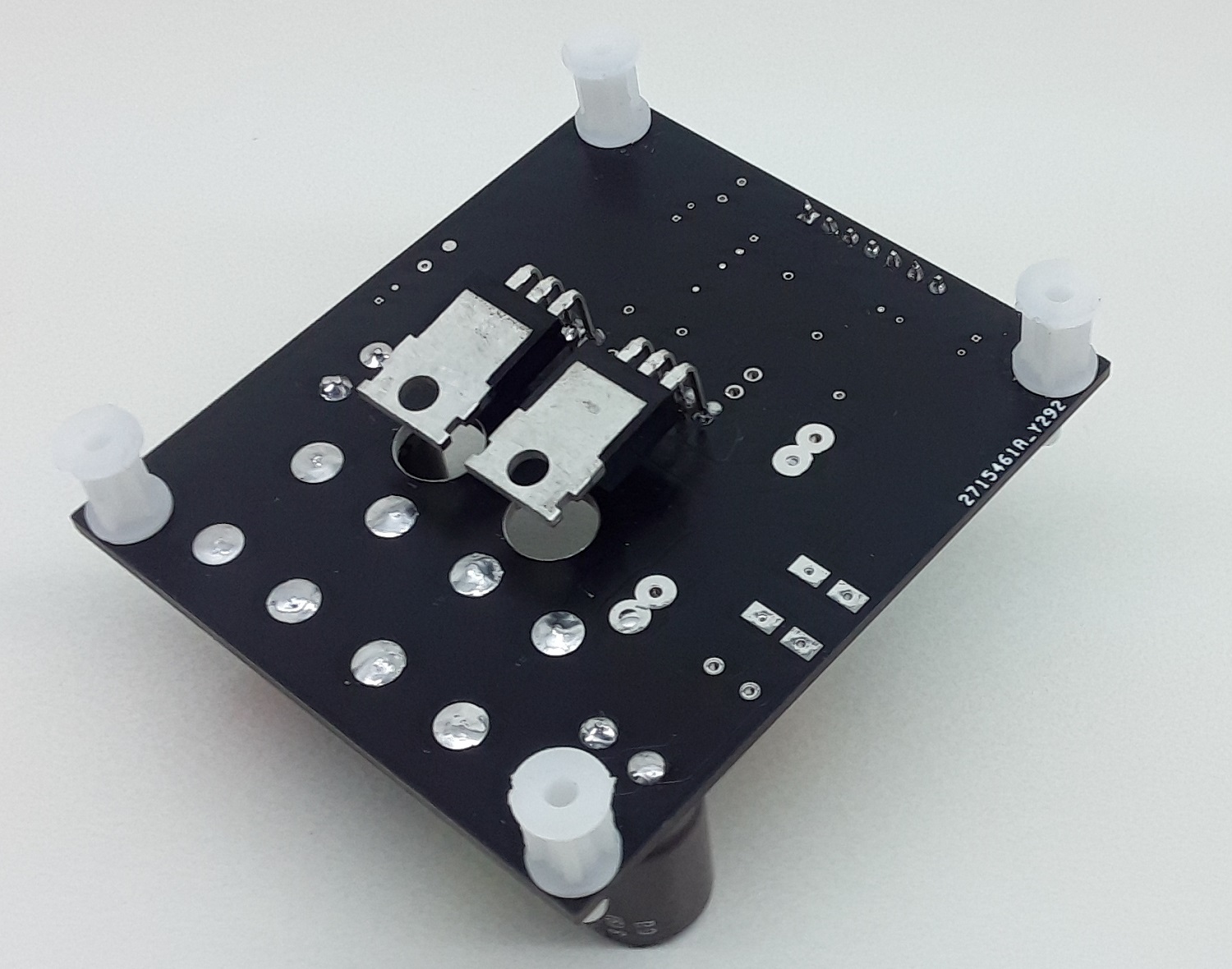
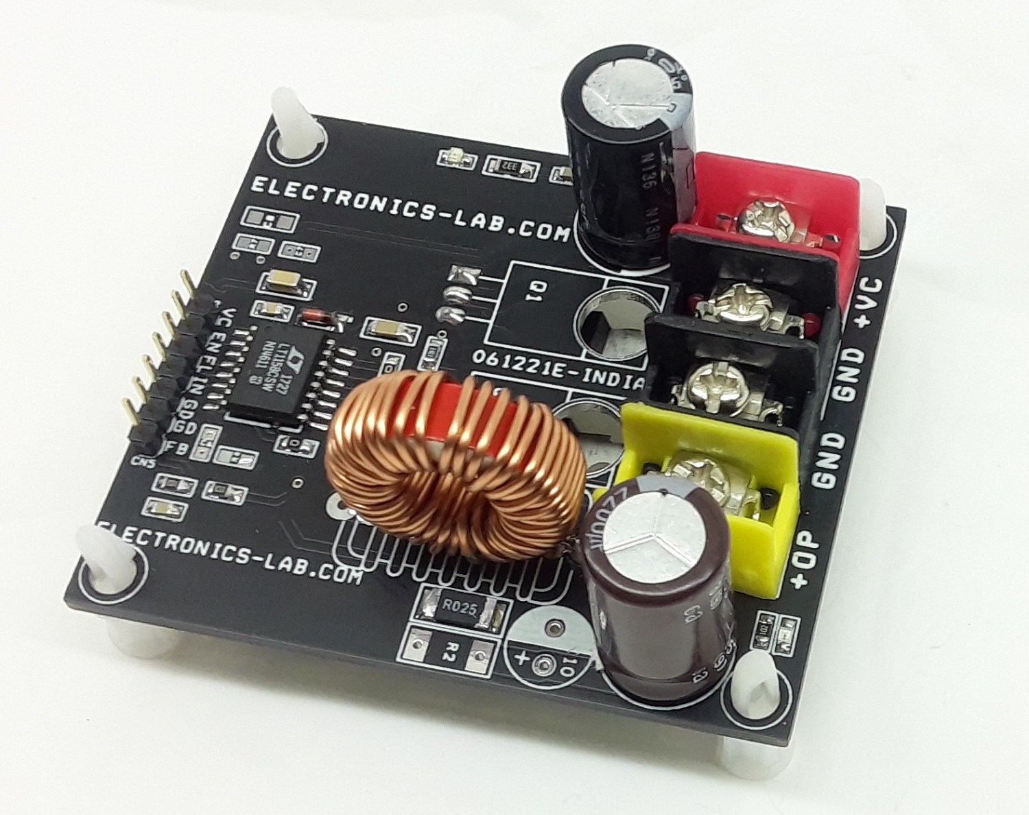
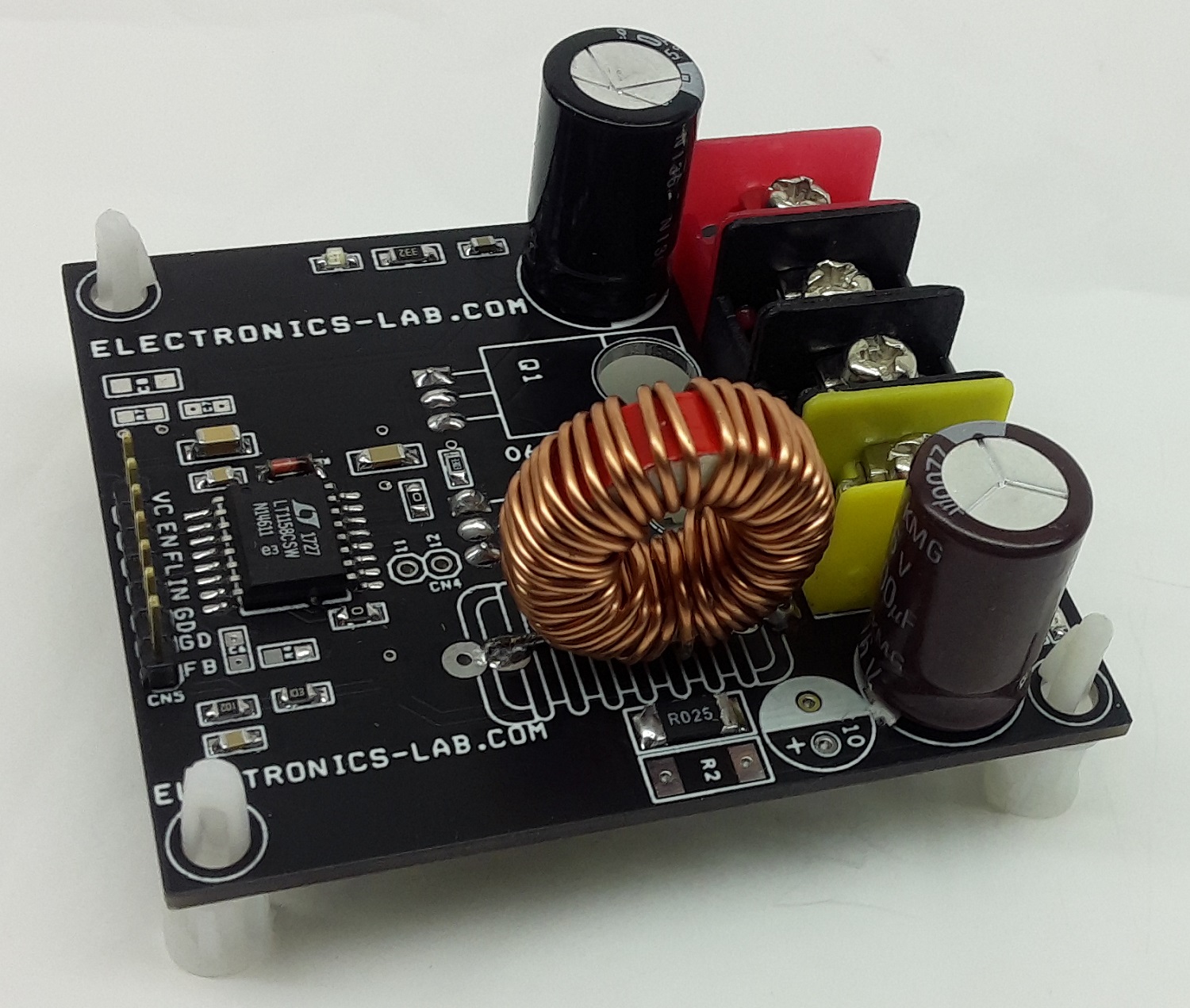
Photos
Video
LT1158 Datasheet
Please follow and like us:
PCB


Subscribe
Login
0 Comments


